Components
The table below lists the parts required for this build.
Parts List
| Image | Component | Role | Quantity |
|---|---|---|---|
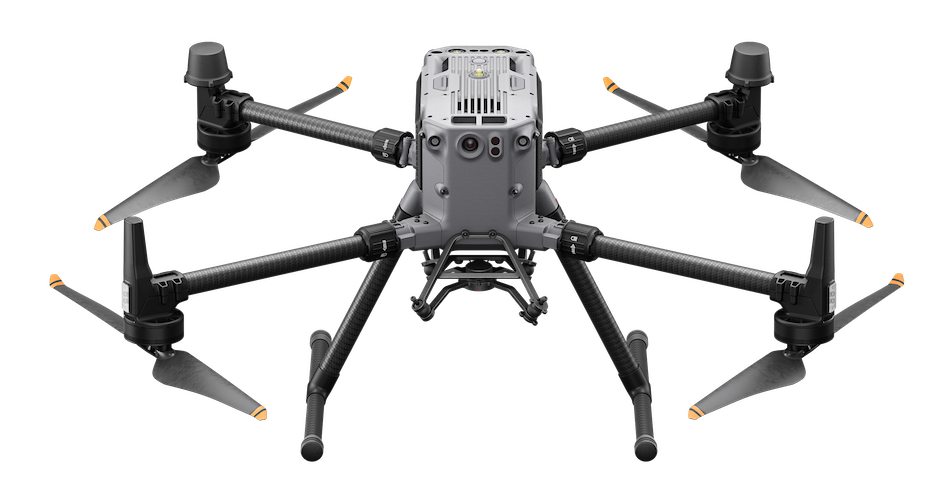 | DJI M350 | Main Vehicle | 1 |
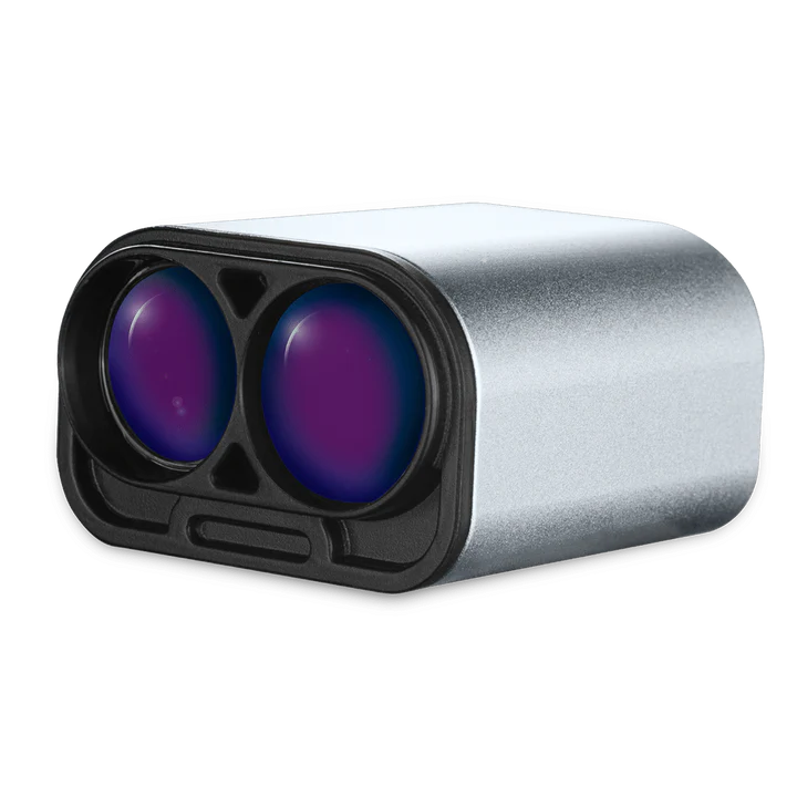 | LW20/C | Landing Deck Plane Detection | 4 |
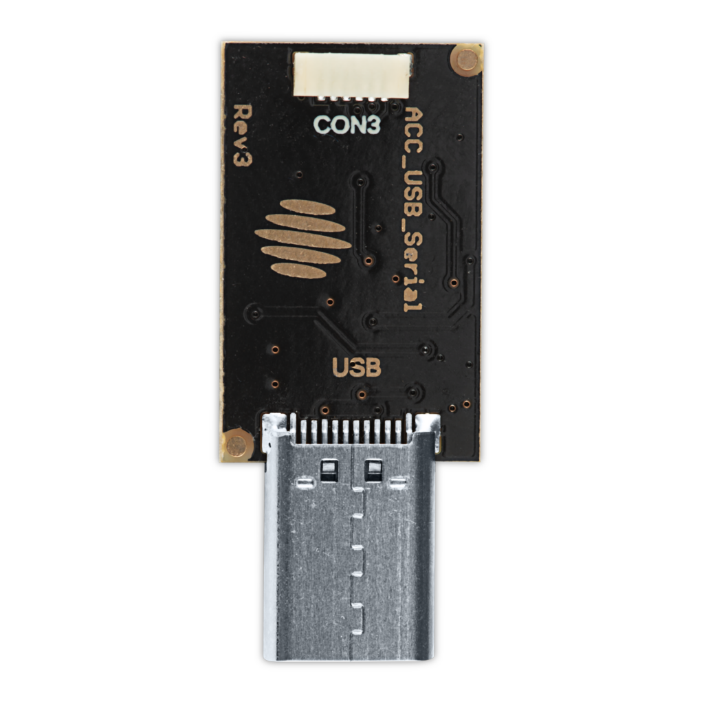 | Generic USB adapter for LW20 | USB connector to configure the LightWare sensors | 1 |
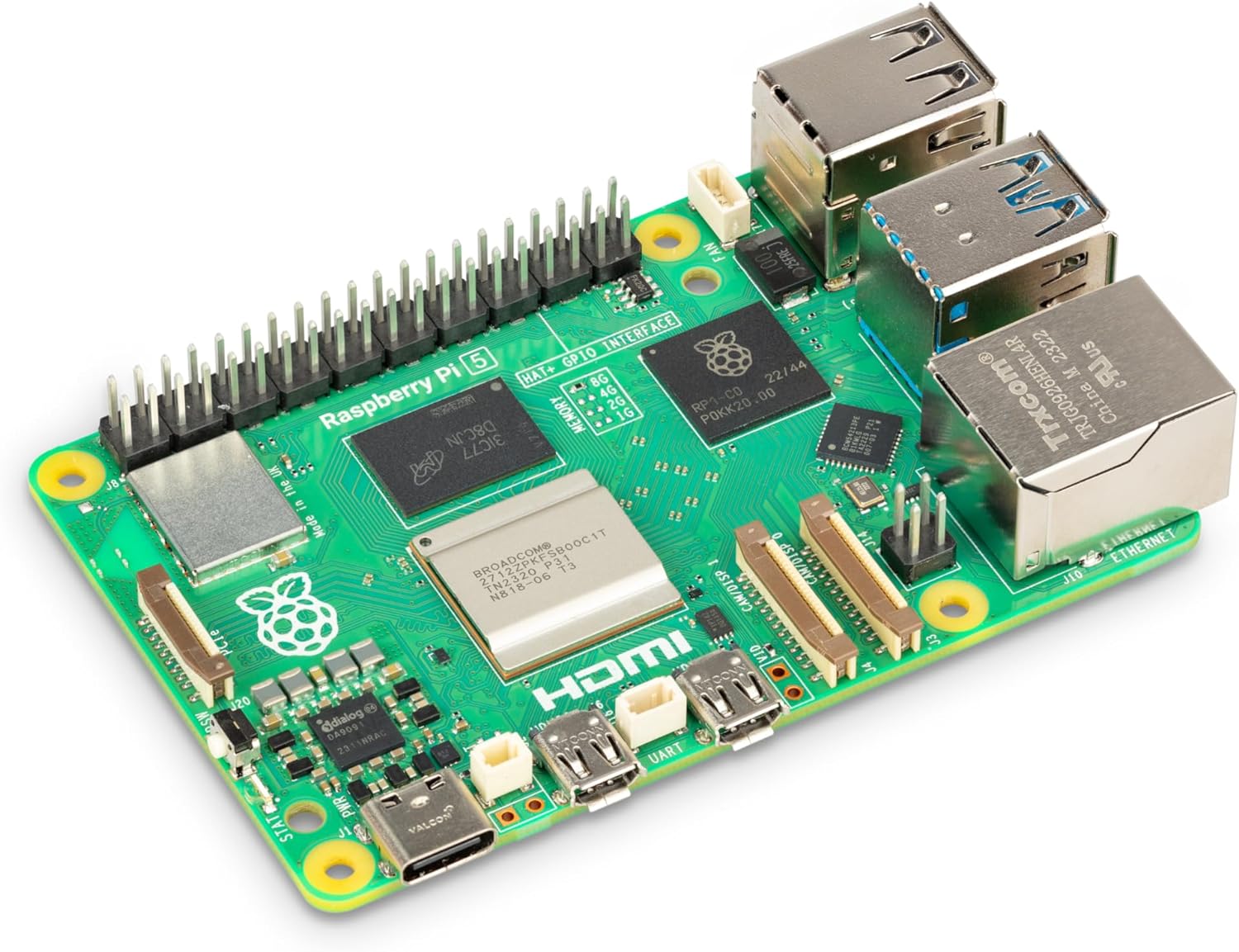 | Raspberry Pi 5 + SD Card | Onboard Compute | 1 |
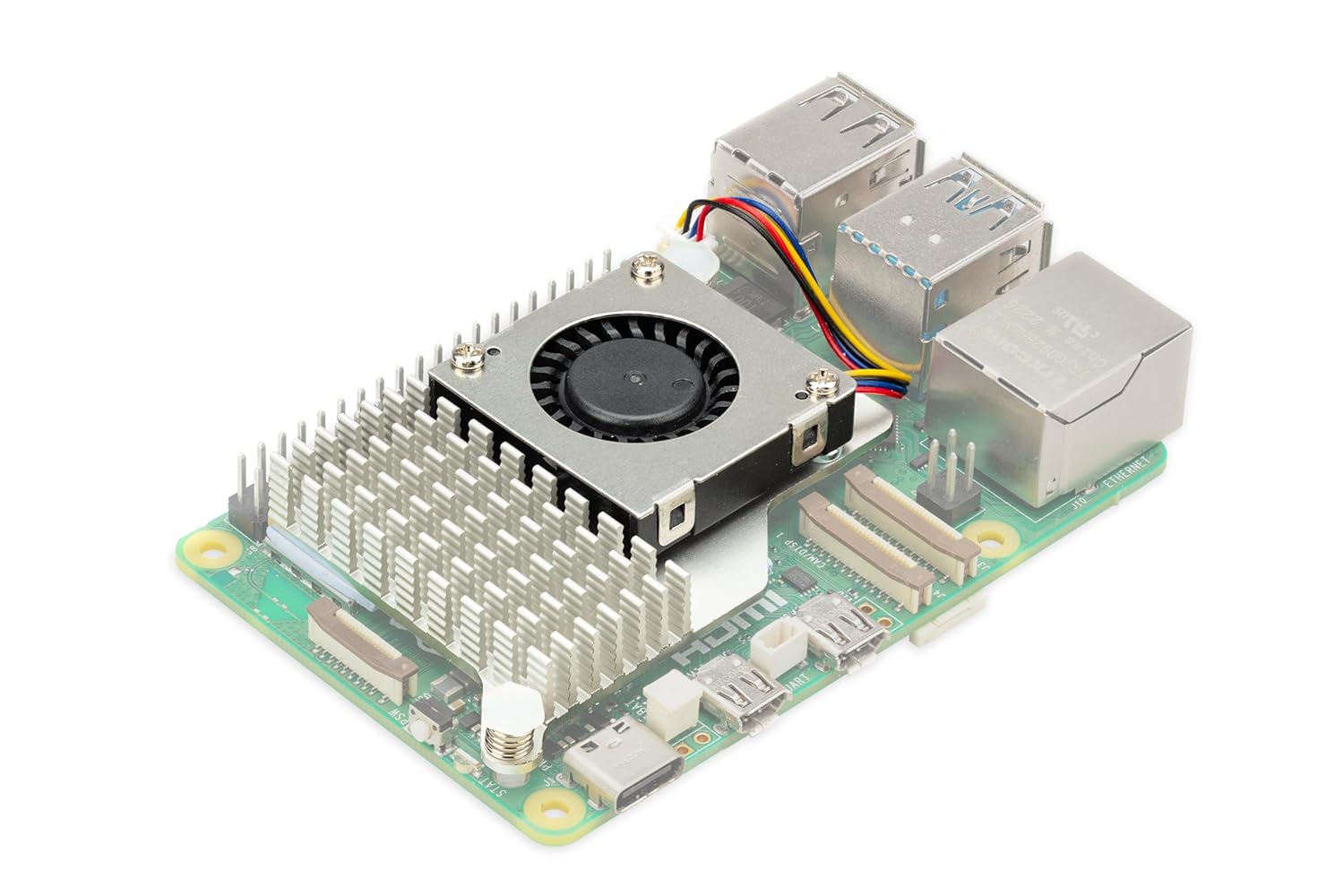 | Raspberry Pi 5 Cooling Kit | Cooling for Onboard Compute Note: This is not strictly necessary for this exercise, but future proofs the setup. | 1 |
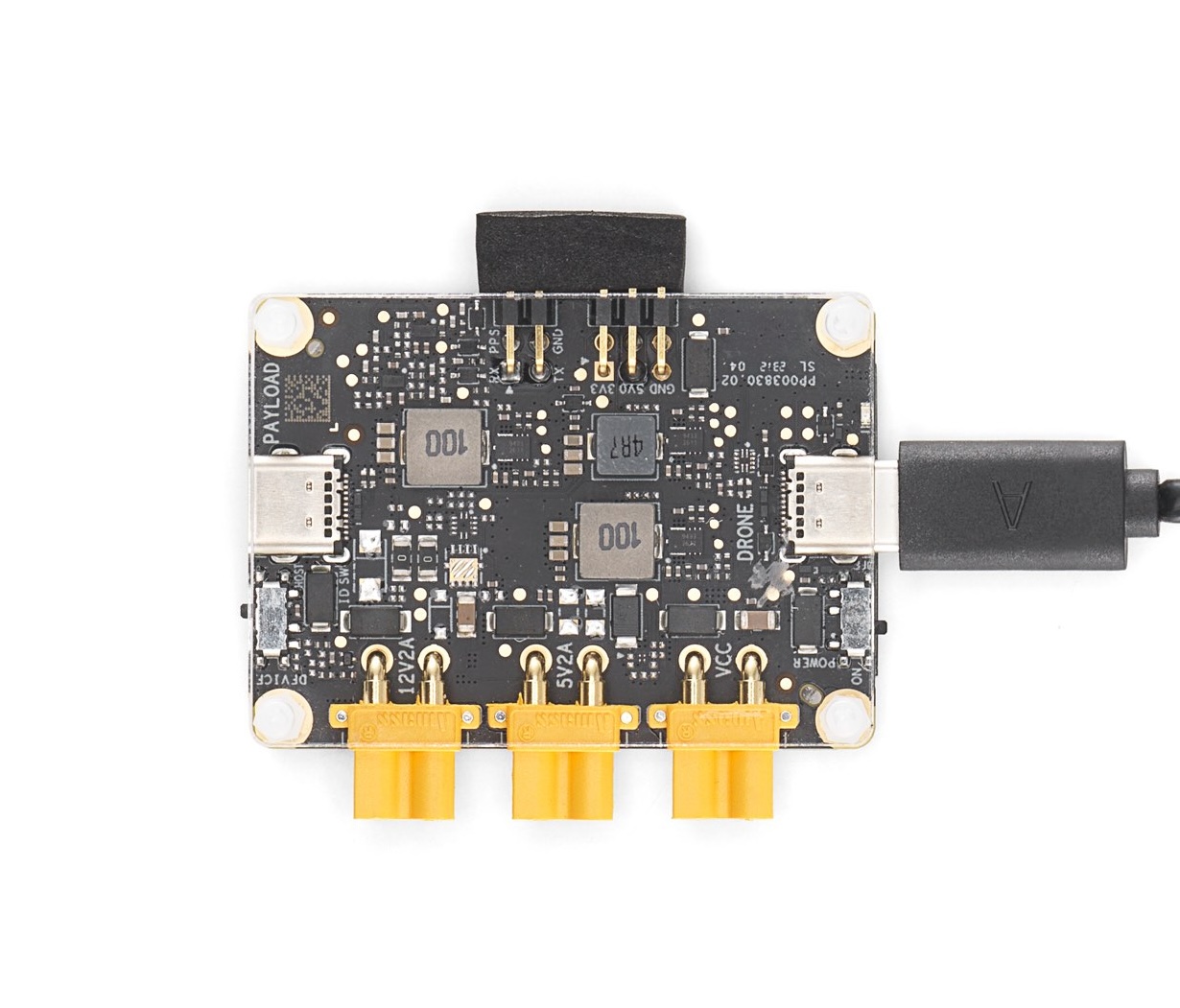 | DJI E-Port Kit | Payload SDK Interface | 1 |
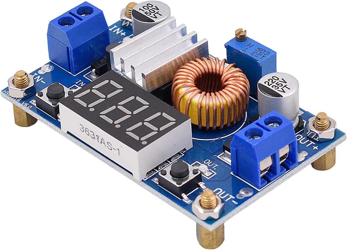 | 5A/5V Voltage Regulator | Voltage regulator for the Pi 5 which requires 5V/5A while the E-Port 5V rail is limited to 2A | 1 |
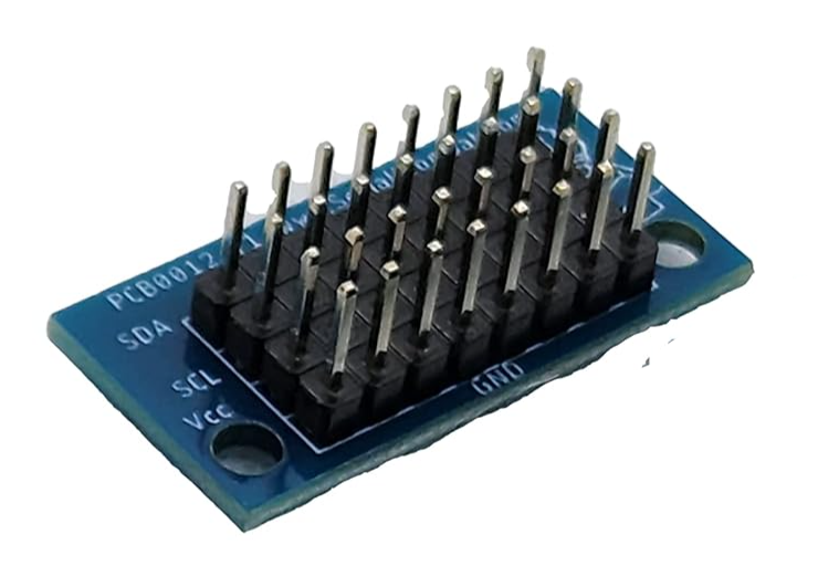 | I2C Breakout Board | Ad-hoc I2C bus hardware for all the sensors | 1 |
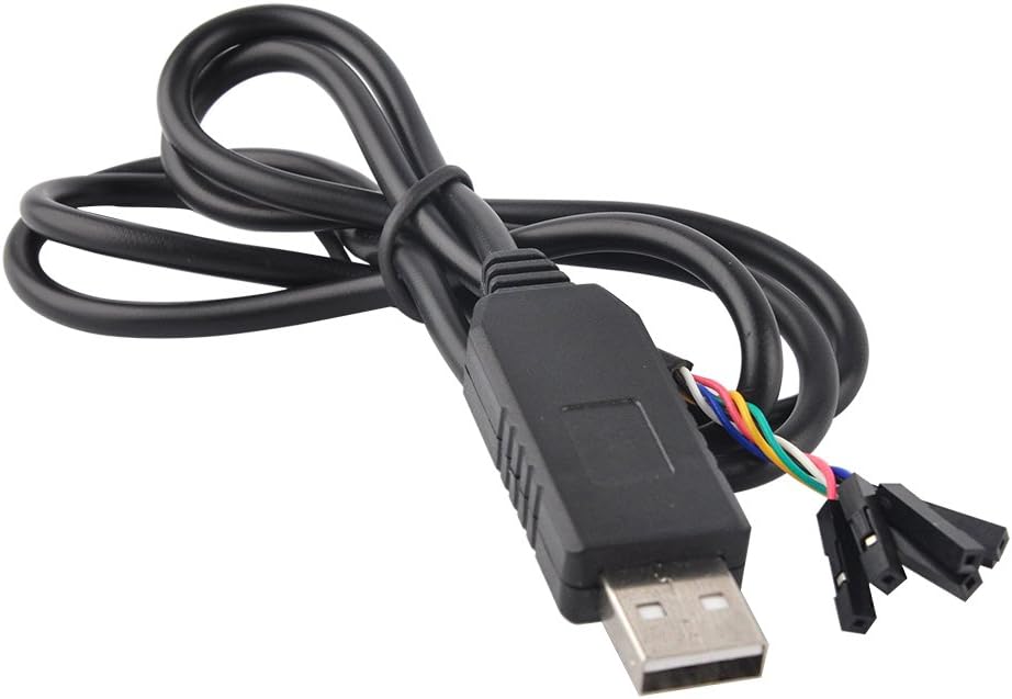 | USB to TTL Cable | Connect the UART from the devkit to the Pi | 1 |
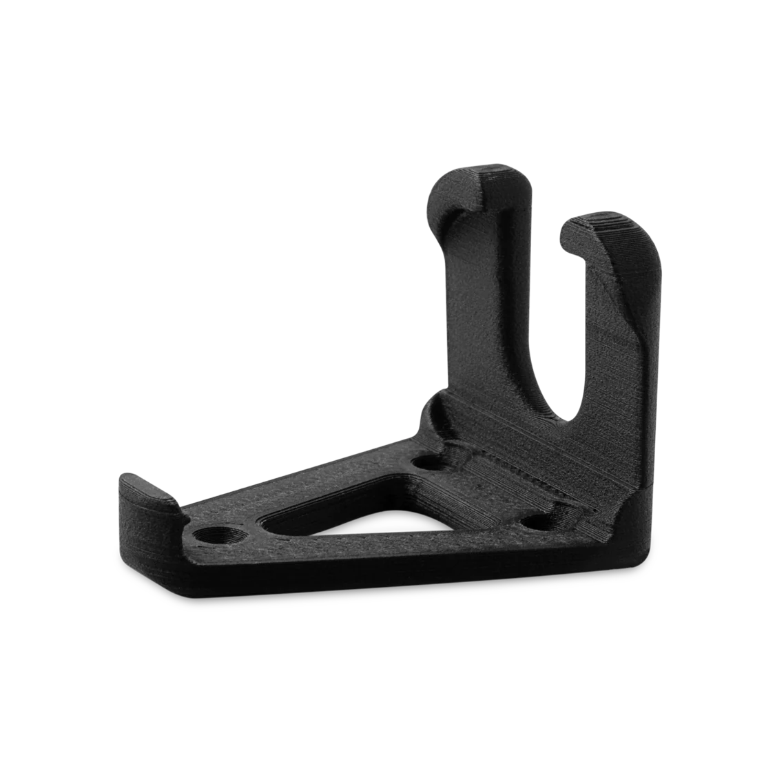 | LW20C Mounting Brackets | Holding the LW20/C against the rails | 4 |
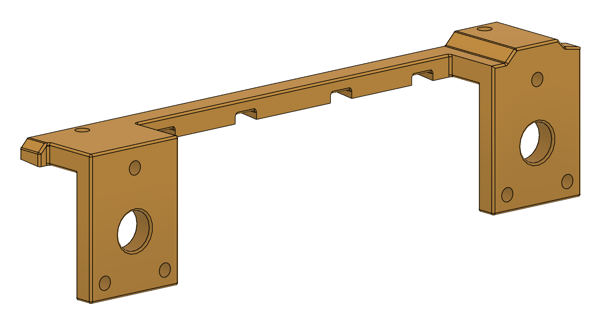 | Lidar Mounting Rails (STEP), (STL) | Holding the LW20/C in an array configuration | 2 |
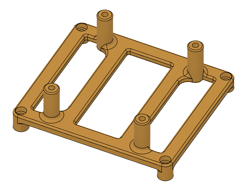 | Compute and E-Port Mounting Kit (STEP), (STL) | Holding the E-Port and the Raspberry pi in place | 1 |
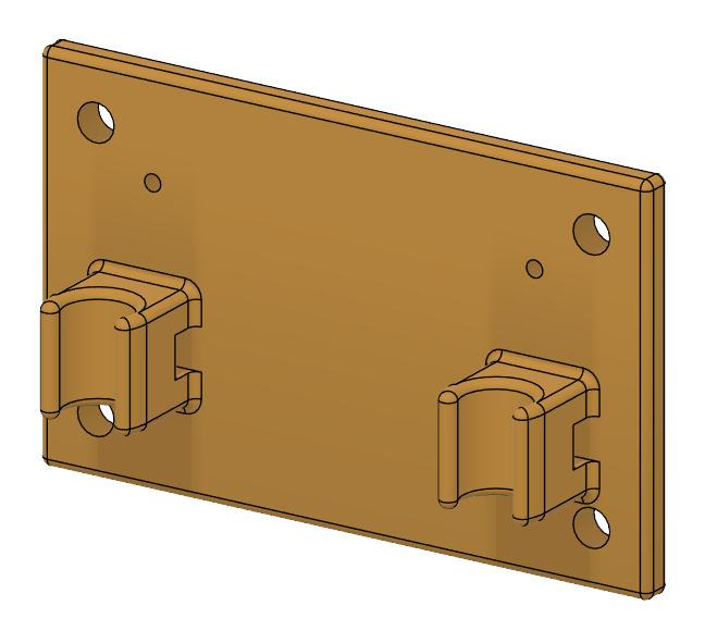 | Voltage Regulator/I2C Bus Mount (STEP), (STL) | Holding the Voltage Regulator and the I2C Bus breakout in place | 1 |
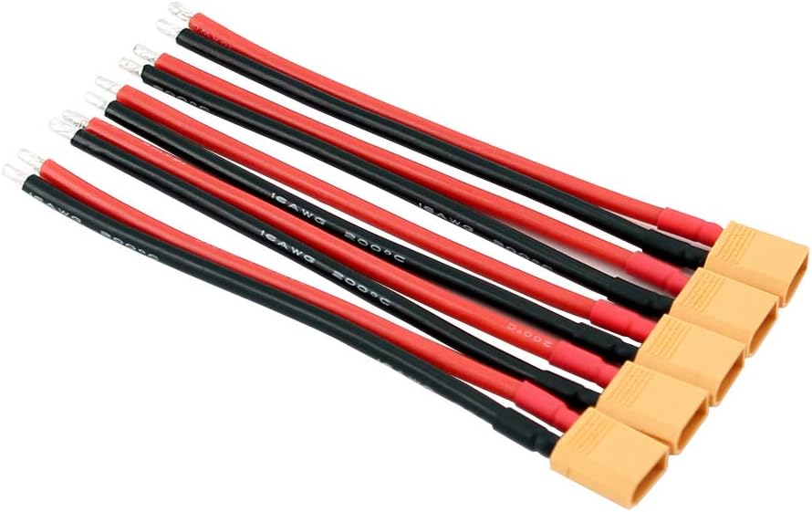 | XT30 Power Cables | Provide power to the voltage regulator. Note: You can make these yourself if you feel up to it. This example uses 16AWG which is much more than needed. | 1 |
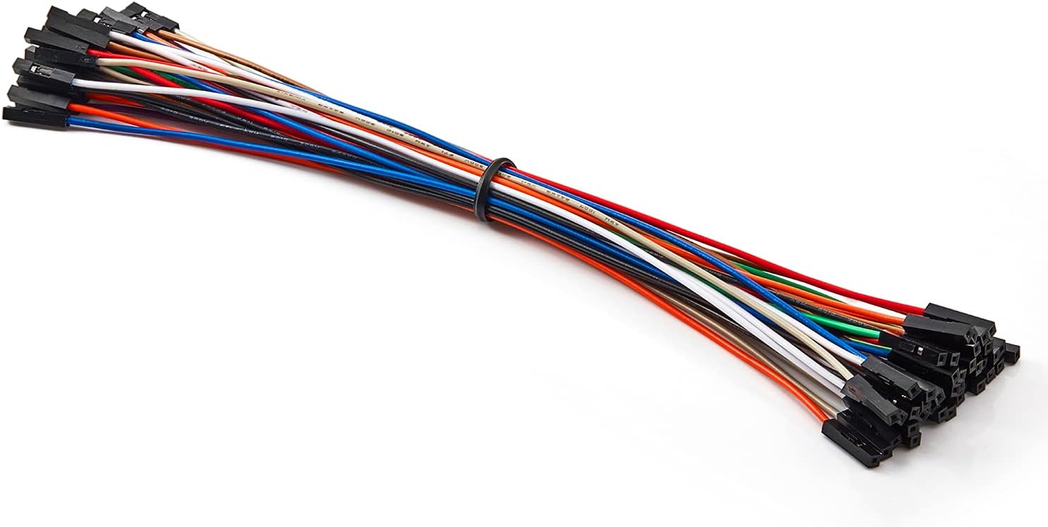 | Female Dupont Cables | Power from voltage regulator to Pi and I2C wiring between Pi and Bus breakout. Note: You can make these yourself if you feel up to it - We're going to crimp the LW20 cables anyway. It's also quite convenient to buy ready made cable and cut/strip them to your need | 6 |
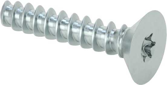 | M1.6 x 8mm Counter Sunk Screws | Secure the clips to the rails | 12 (4x3) |
 | M2.5 x 4mm Heat-set Insert | Allows to attach he voltage regulator and easily remove/reinstall | 4 |
 | M3 x 4mm Heat-set Insert | Allows to attach he voltage regulator and easily remove/reinstall | 4 |
 | M2.5 x 6mm Screws | Secure the Raspberry Pi to the Mount | 4 |
 | M3 x 6mm Screws | Secure the Voltage Regulator and the I2C Breakout to the Mount | 6 |
 | M3x8mm Standoffs | Used to elevate the voltage regulator and the I2C breakout | 6 |
 | M3 x 8mm Screws | Secure the Back Compute/E-port Mount & Back of the rails to the Vehicle | 4 |
 | M3 x 10mm Screws | Secure Front of the rails to the Vehicle | 2 |
 | M3 x 15mm Screws | Secure the Front Compute/E-port Mount | 2 |
 | Zip Ties - 6 inch | Secure Cables to Lidar Rails and top mount | 3-5 |
 | BluTack | Secure the EPort and Cables to the vehicle | 1 |
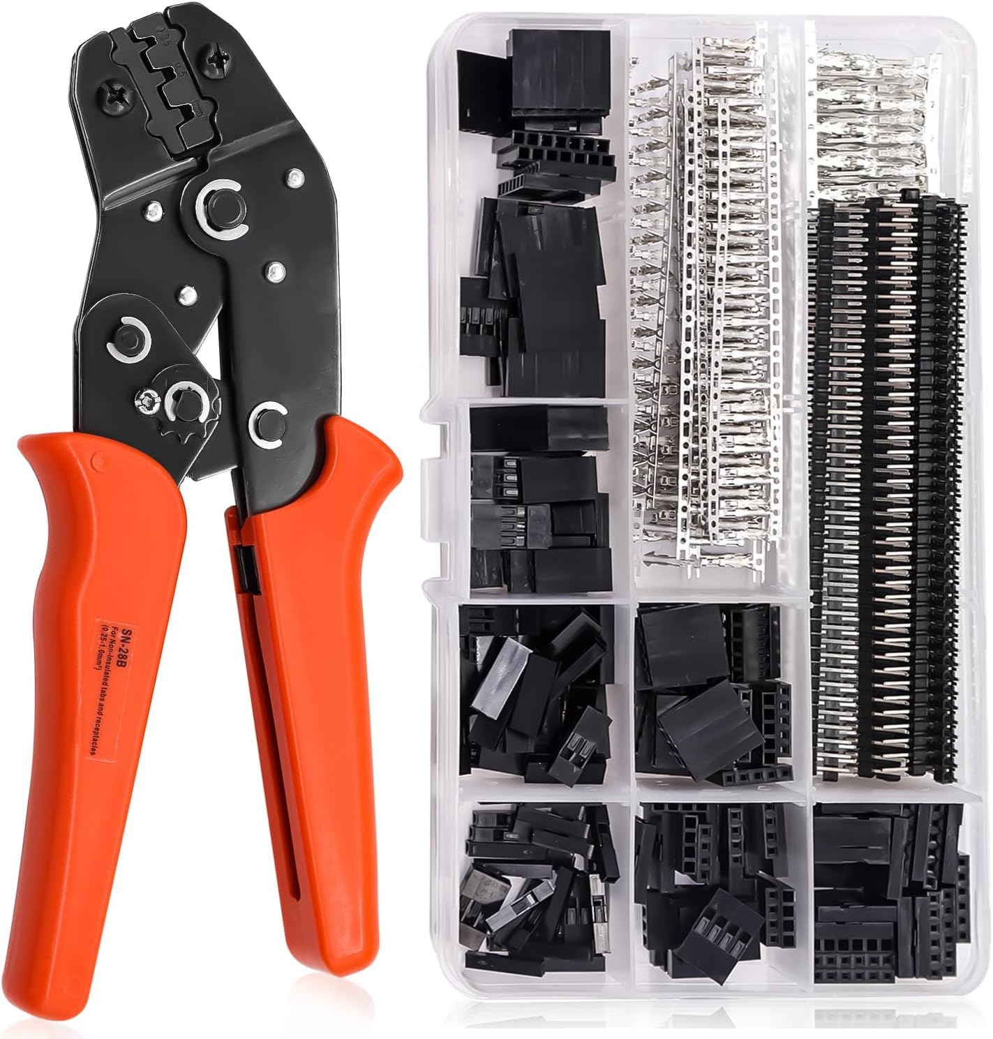 | Dupont Female headers + Crimper | Simple connection of the LW20/C to the Raspberry Pi | 1 |
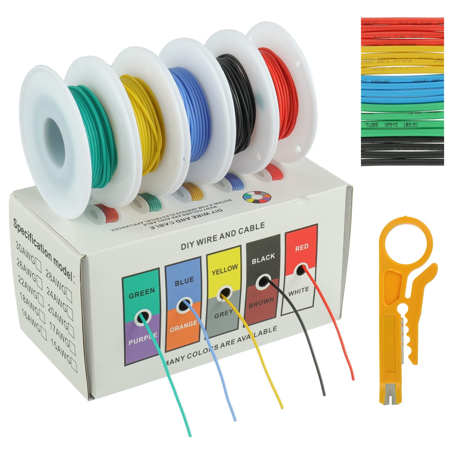 | 28AWG silicon wire kit | Misc. Wiring | 1 |
DJI M350
The DJI M350 is a reliable workhorse, well-suited for demanding inspection tasks. With its Payload SDK capabilities and compatibility with a range of top-tier payloads, it has established itself as a trusted choice for complex operations. Its durability and versatility make it an excellent platform for this project, ensuring consistent performance in real-world scenarios.
LW20/C
The selected LiDAR in this application is the LightWare LW20/C LiDAR due to its impressive range and compact form factor. While multi-point or 3D LiDAR options may seem appealing, they are unnecessary for this scenario, adding unwanted weight that would significantly impact the drone's flight performance and endurance. By opting for a small, precise LiDAR unit and utilizing software to maximize its capabilities, a lightweight yet highly effective solution that meets all operational requirements is achieved.
Raspberry Pi 5 + E-Port Kit��
The Raspberry Pi 5 is desirable for its balance between computational power and availability. As a mid-size computer, it offers ample processing capability while being easy to source. While alternatives may exist that provide either a smaller footprint with lower power or higher power with a larger footprint, the Raspberry Pi 5 offers more than enough power for this specific scenario.
The E-Port Kit provides a simple and cost-effective solution for connecting the required peripherals, and it is widely available.
While these components are sufficient for a functional prototype, they lack the refinement of a polished product. Once the solution has been validated, the next logical step would be to develop a custom compute module and E-Port breakout board in a more integrated package - something that is easily achievable after validating product capabilities.
Mounting Hardware
The LW20/C is mounted in a position that ensures optimal performance while staying clear of other critical components. The mounting hardware is LightWare's LW20/C bracket, which can easily acquire from our Store, or be 3D printed using the CAD files available in the LightWare Resource Center.