Hardware
Sensor settings and firmware
Each LightWare LW20/C is pre-configured an I2C address of 0x66. To differentiate the four devices on the bus, each device will have to be configured with a unique address.
Configuration of the LightWare devices is accomplished with LightWare Studio.
Connect each sensor to the Generic USB adaptor. Update the firmware and change the I2C address as described in the Product Guide.
LightWare Studio denotes the I2C addresses in decimal. The table below shows four decimal values for the corresponding hexadecimal values.
| Decimal | Hex |
|---|---|
| 102 | 0x66 |
| 103 | 0x67 |
| 104 | 0x68 |
| 105 | 0x69 |
Mark each sensor with its address as their position on the aircraft will be relevant for future logic setups.
Assembling the hardware
Sensor mounting
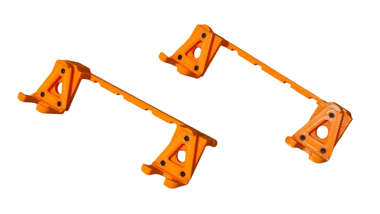
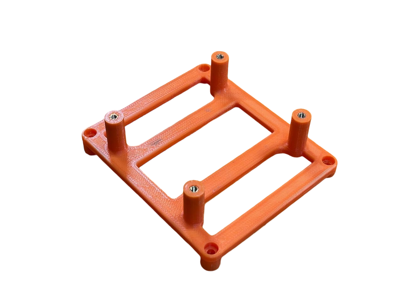
Start by preparing the mounting rails and clips that will hold the sensors securely on the underside of the aircraft.
Attach the mounting clips to the rails, which will later be secured to the drone. Using countersunk screws, fasten the clips as demonstrated in the image below to ensure a snug and stable fit for the sensors.
Communications cable preparation
Strip the pre-attached LightWare connector from the end of the communications cables from each of the LiDAR sensors and prepare the cable for connecting the Dupont connectors.
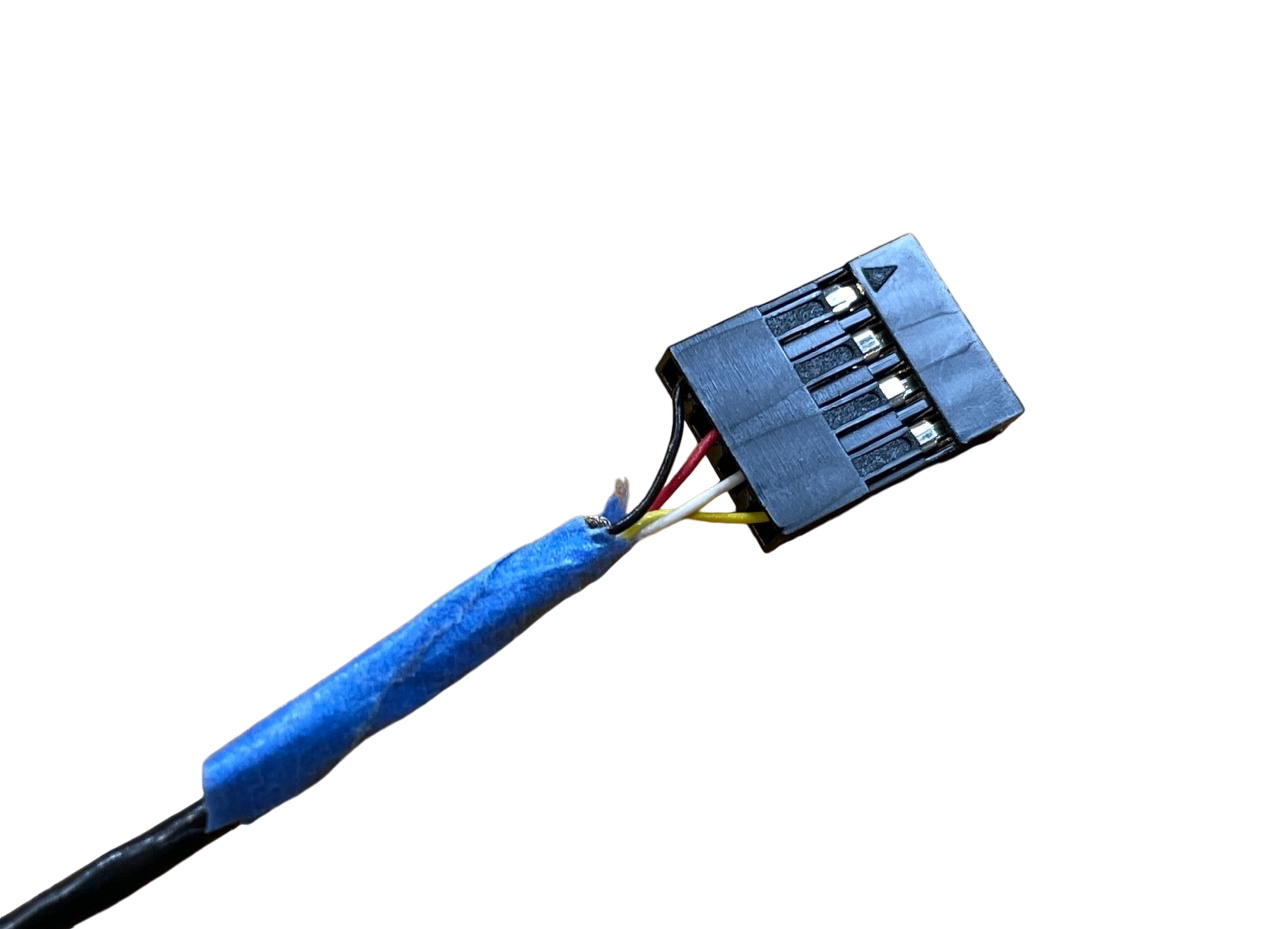
Connect the black (GND), red (VCC), white (RX/SCL), and yellow (TX/SDA) wires from the LW20/C and crimp each one individually using Dupont connectors. Ensure each wire is firmly secured within its connector to avoid any loose connections.
Once crimped, insert the wires into a single 4-pin Dupont housing in the following order:
- Black (GND)
- Red (VCC)
- White (RX/SCL)
- Yellow (TX/SDA)
This will ensure proper alignment for easy connection to the appropriate ports on the onboard computer or other components.
Double-check that the wires are inserted in the correct order and securely held within the connector housing.
Mounting the sensors
Begin by attaching the 3D-printed bracket to the underside of the M350 drone. Carefully flip the aircraft upside down - it's best to do this step now since the computer will be installed later.
Remove the payload screws and set them aside in case it is needed to detach the kit in the future.
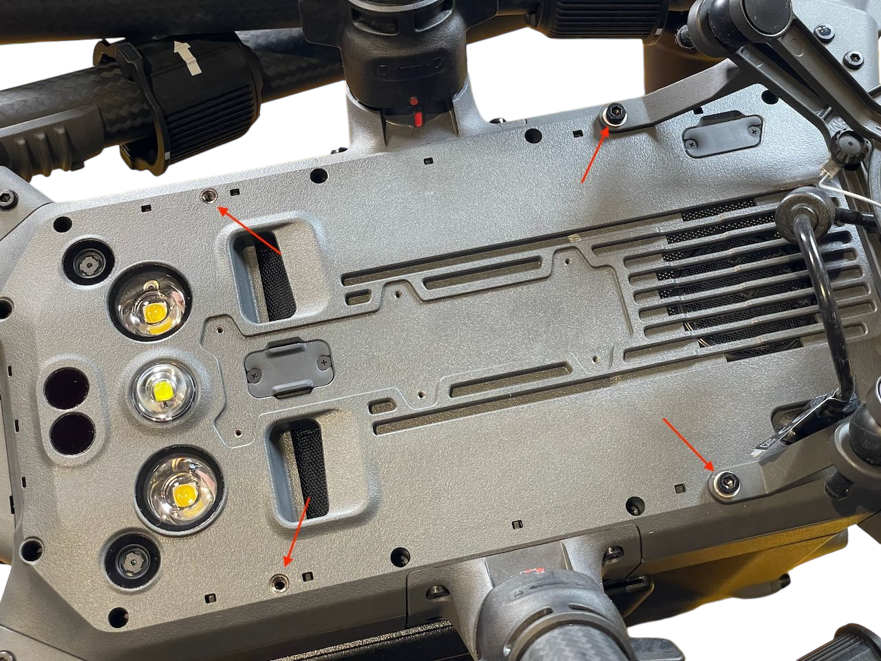
Secure the rails to the drone using M3x10mm screws for the front (where the payload is located) and M3x8mm screws for the back.
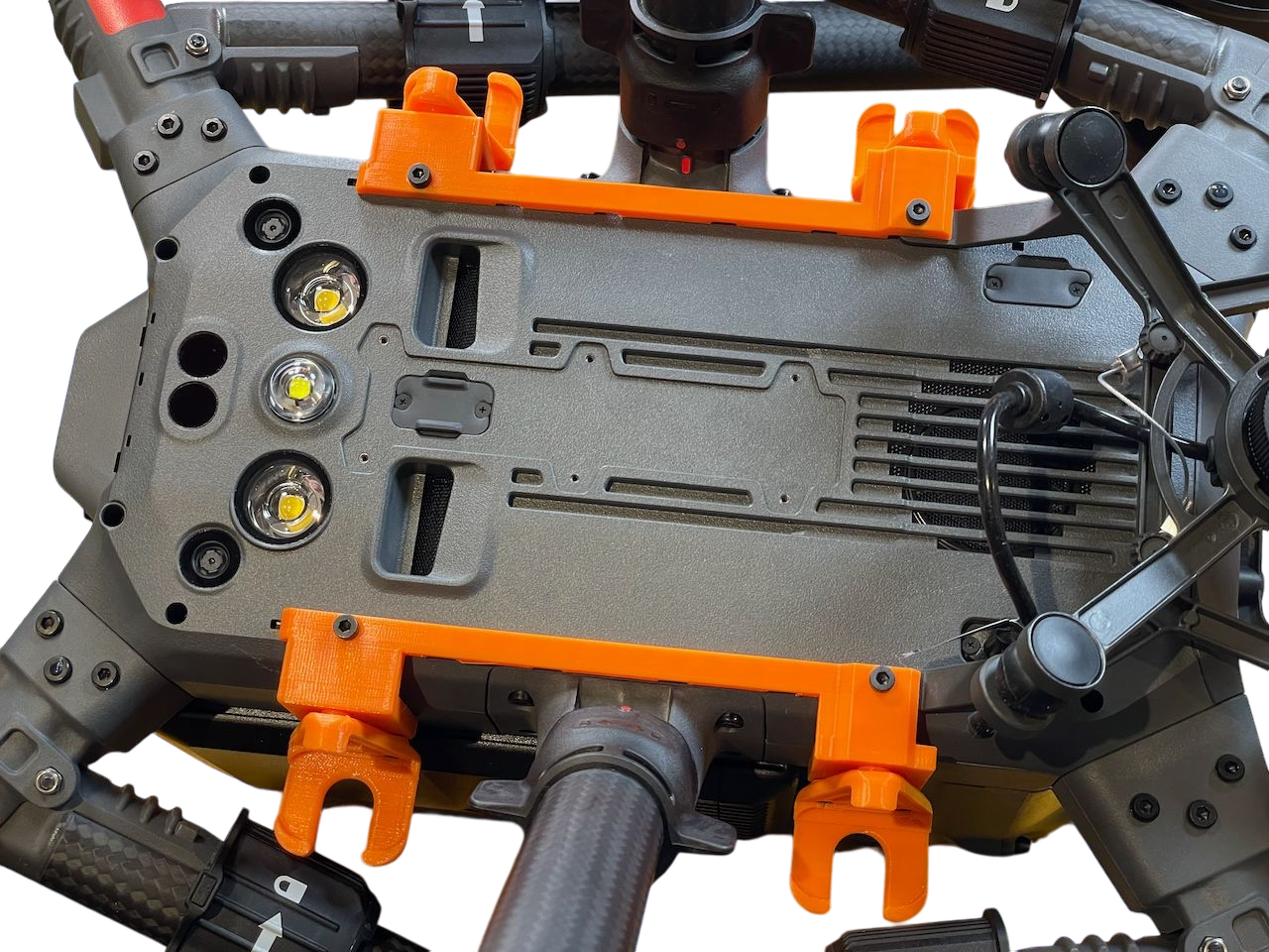
Next, clip the sensor onto the 3D-printed bracket. To manage the cables, use adhesive putty (like Blu Tack or similar) to keep them neatly secured against the body of the aircraft.
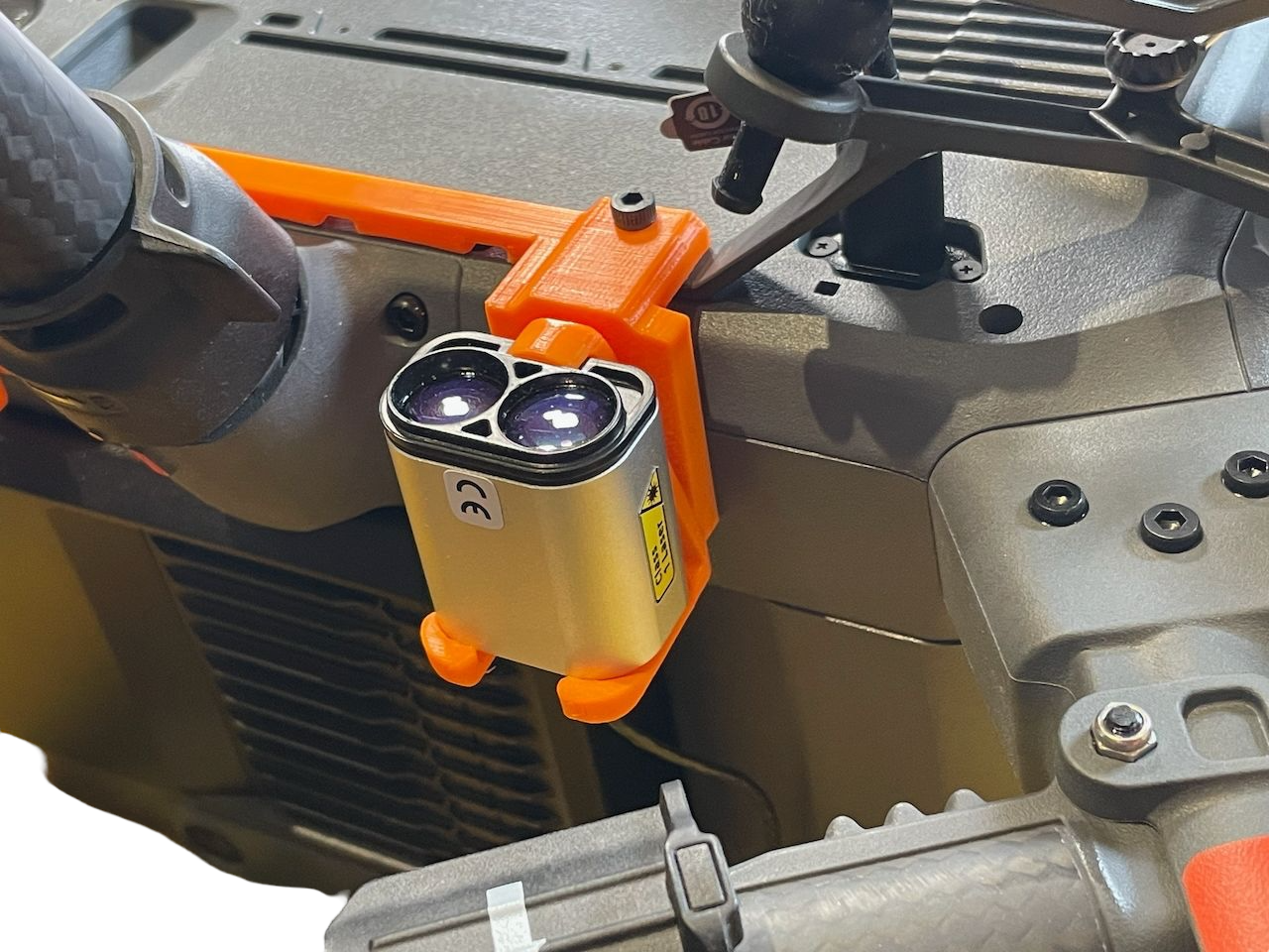
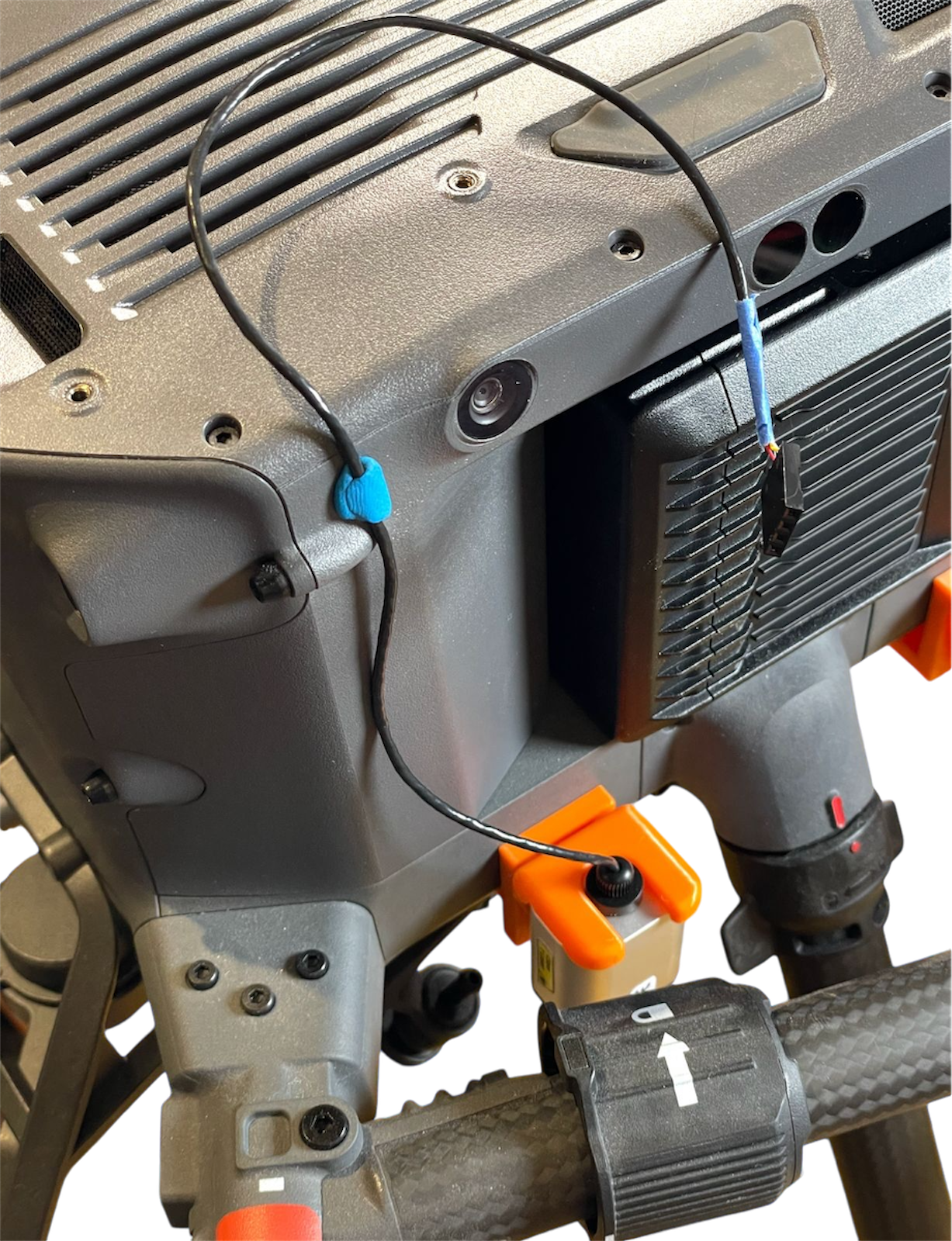
For production deployments, there are more durable methods to secure the cables, including printing a cable guide brace between the two mounting brackets. This guide focuses on R&D and quick validation of the end-to-end system. An alternative option would be to route the cables through the rails and secure them with zip ties. The rails are designed to accommodate this. The wire length may need to be extended for the rear sensors. The cables can also be guided along the side of the aircraft using adhesive putty, taking care not to obstruct the view of the obstacle avoidance sensors.
Preparing the compute unit mounting
Use M2.5 heat-set inserts for the Raspberry Pi posts on the compute mount. Use a soldering iron at the melting temperature appropriate for the plastic used in the printing of the mount. Carefully insert the heat-set and remove the iron once the insert is sufficiently embedded.
The heat-set inserts are optional but recommended for a more secure fit. An alternative would be to use self-tapping screws directly into the plastic mount.
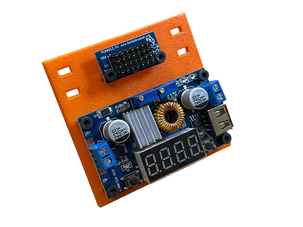
Preparing the voltage regulator mounting
The voltage regulator which will supply power to the Raspberry Pi and the I2C breakout board.
Install the heat-set inserts into the board, following the same process used previously. Use a soldering iron at the appropriate temperature to ensure the inserts are securely in place.
When using an alternative I2C bus and voltage regulator configuration, ensure that the required power is supplied for the Raspberry Pi to function properly.
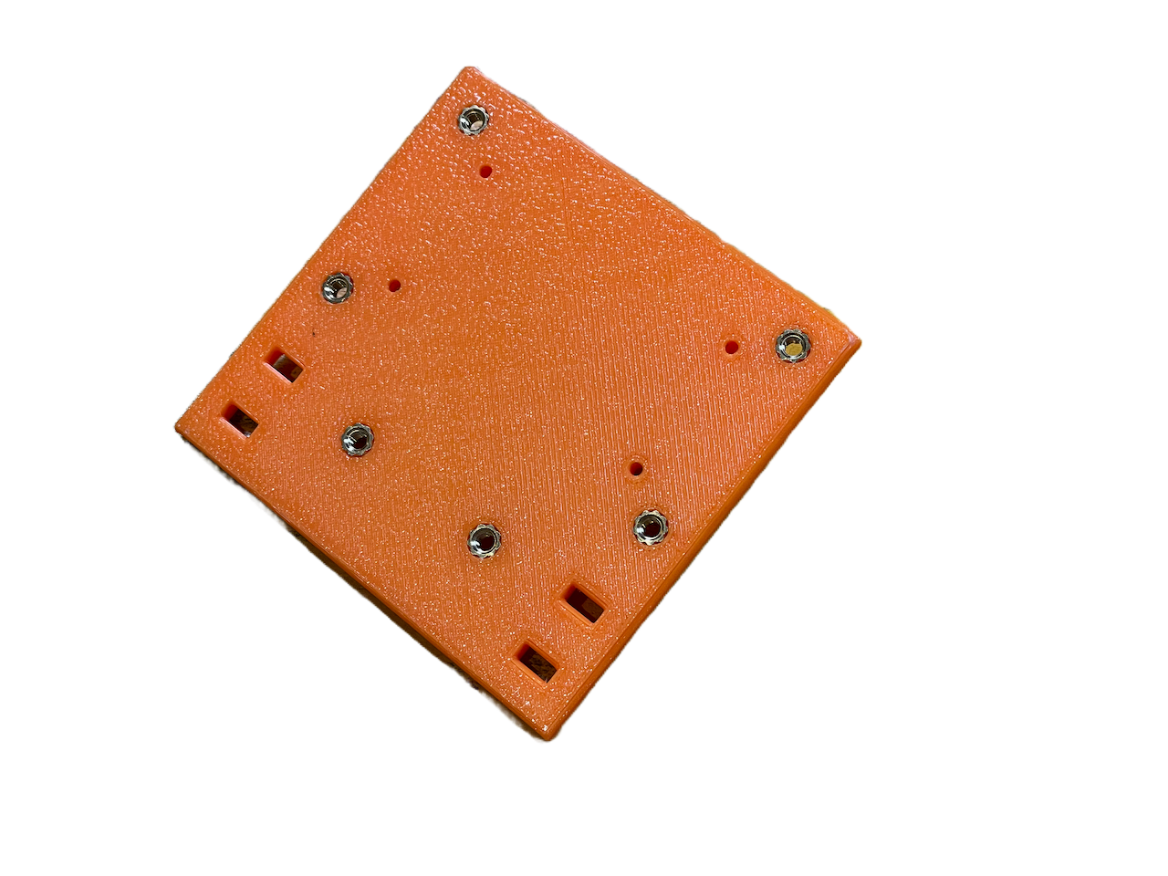
Mounting the E-Port kit
The E-Port Kit will be positioned underneath the Raspberry Pi. Place the E-Port kit as seen on the picture below, aligning the E-Port kit inside the securing post.
Secure the board to the mount using a zip tie.
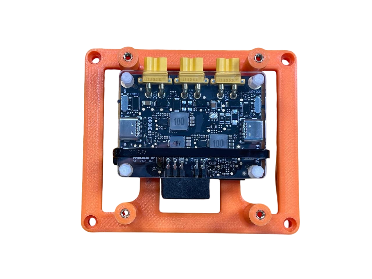
Ensure that the "Drone" USB-C port on the E-Port Kit is facing the starboard (right) side of the mount. This orientation is crucial for proper functionality.
Verify that the E-Port Kit is firmly in place before proceeding to the next step.
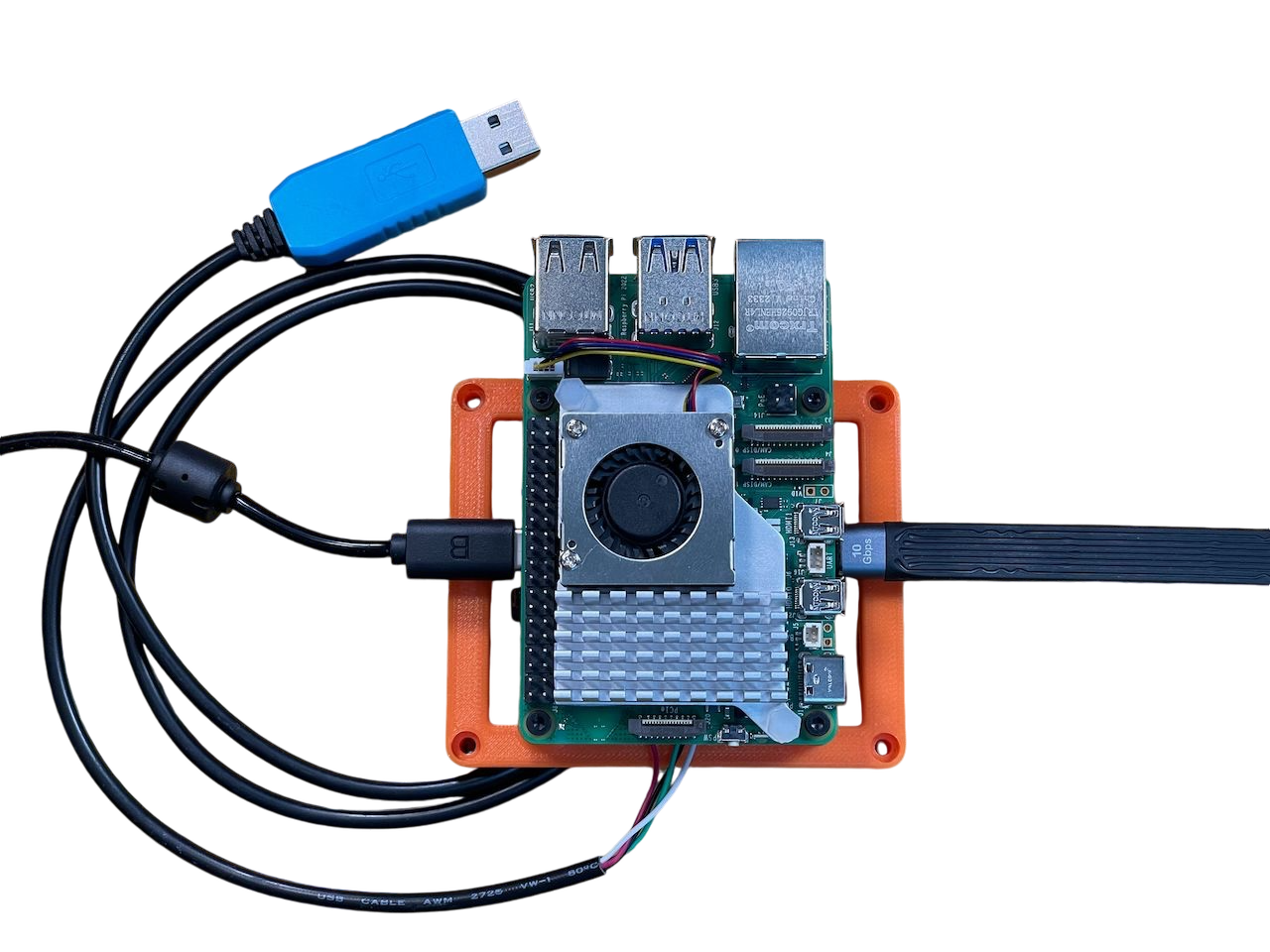
Connect the USB/TTL cable
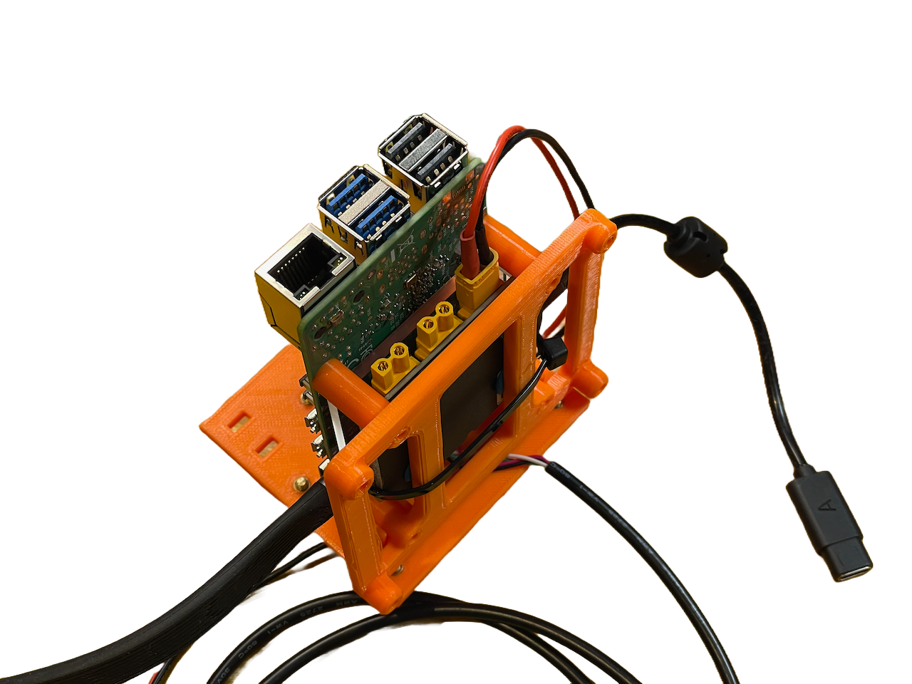
While having a clear view of the markings on the PCB, and before moving on to the Raspberry Pi, connect the USB/TTL cable to the pins on the E-Port Kit.
Connect the USB-C cable from the kit, ensuring that the "B" side of the cable is facing upwards.
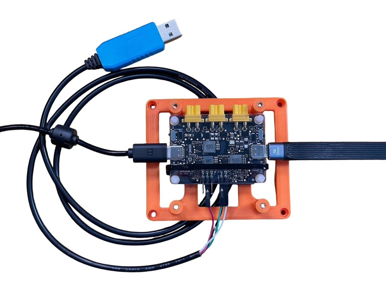
The USB-C cable used for DJI development is not reversible. Pay close attention to the "A" and "B" side orientations as specified in the DJI developer documentation.
Do not connect the cable to the aircraft.
Mounting the Raspberry Pi
The mount provide is designed for through-hole installation compatible with the bare board or the official Raspberry Pi case.
Use M2.5x6mm screws to attach the Raspberry Pi to the mount, ensuring that the connectors are facing the back of the aircraft.
Be careful not to overtighten the screws to avoid damaging the board.
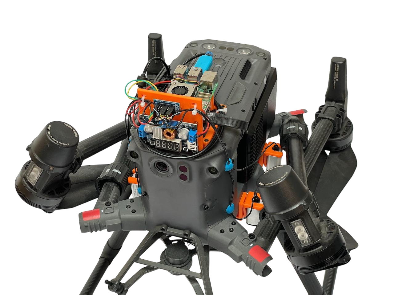
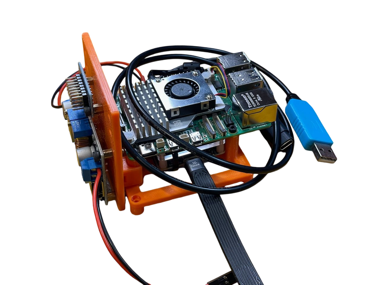
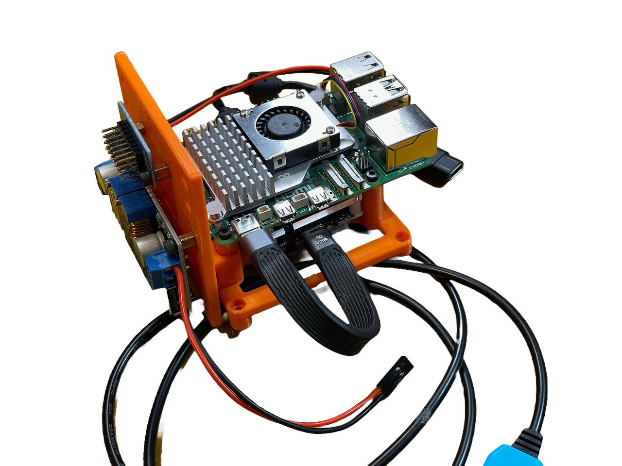
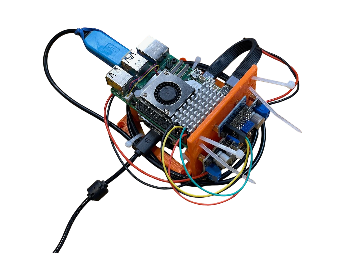
Confirm the assembly
Based on the preceding steps, the design should have the following configuration.
Secure the voltage regulator and I2C breakout
Use M3x6mm screws to securely attach both the voltage regulator and the I2C bus breakout to the side board.
Ensure that both components are firmly secured to prevent any movement during operation.
Attach the E-Port power cable to the input terminals of the voltage regulator and the Raspberry Pi power cable to the output terminals of the voltage regulator.
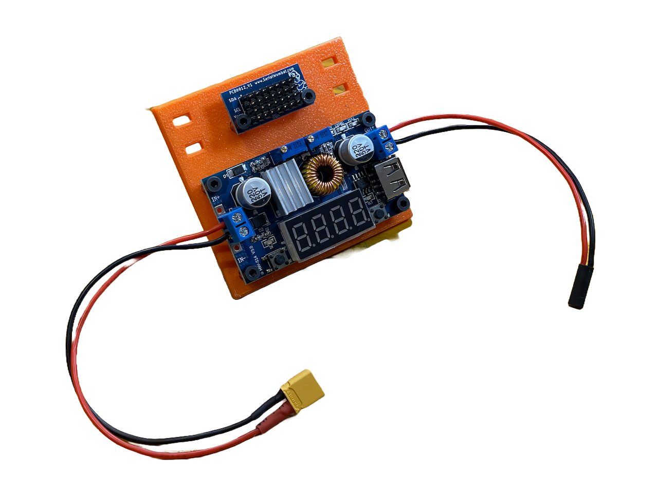
Ensure that no power is supplied to the voltage regulator at this point. The correct voltage will be configured in a later step.
Adding the Raspberry Pi
Follow the provided instructions to set up the SD card for the Raspberry Pi: Follow these instructions to get it done
Once complete, insert the SD card into the slot on the Raspberry Pi. Clip the side board to the front of the Raspberry Pi's mount.
The round clip would be enough to secure it, but if you want, you can secure them further with zip ties.
Attach the XT30 power cable to the unregulated power connector on the E-Port Dev Kit.
Plug the short USB-C cable into the device USB port on the E-Port Dev Kit and the other end into the Raspberry Pi's USB port - this will act as the fast data line.
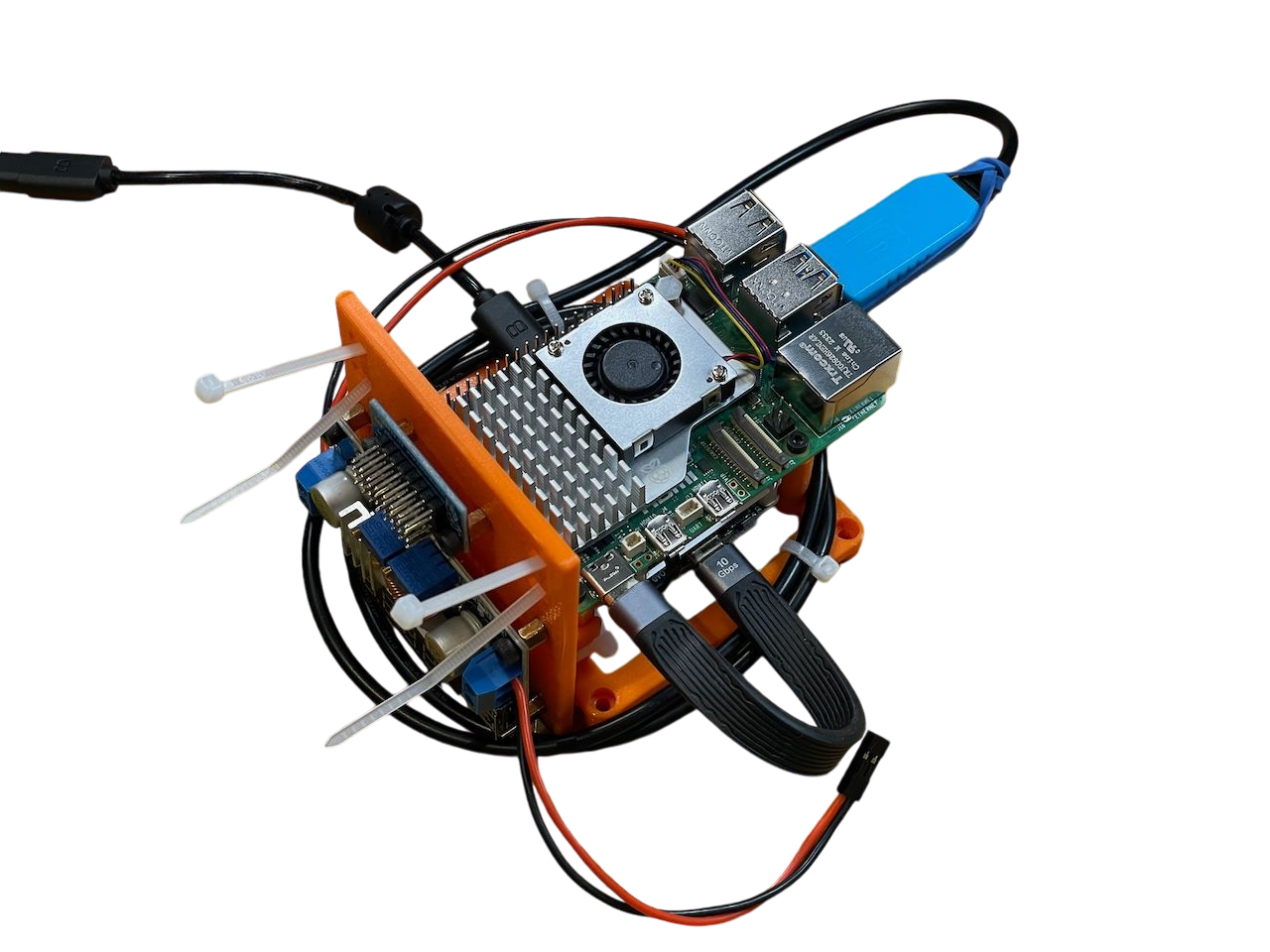
Coil the USB to TTL cable around the base of the mount and connect the USB-A end to one of the Raspberry Pi's USB ports. Secure the cable against the frame with zip ties, if desired.
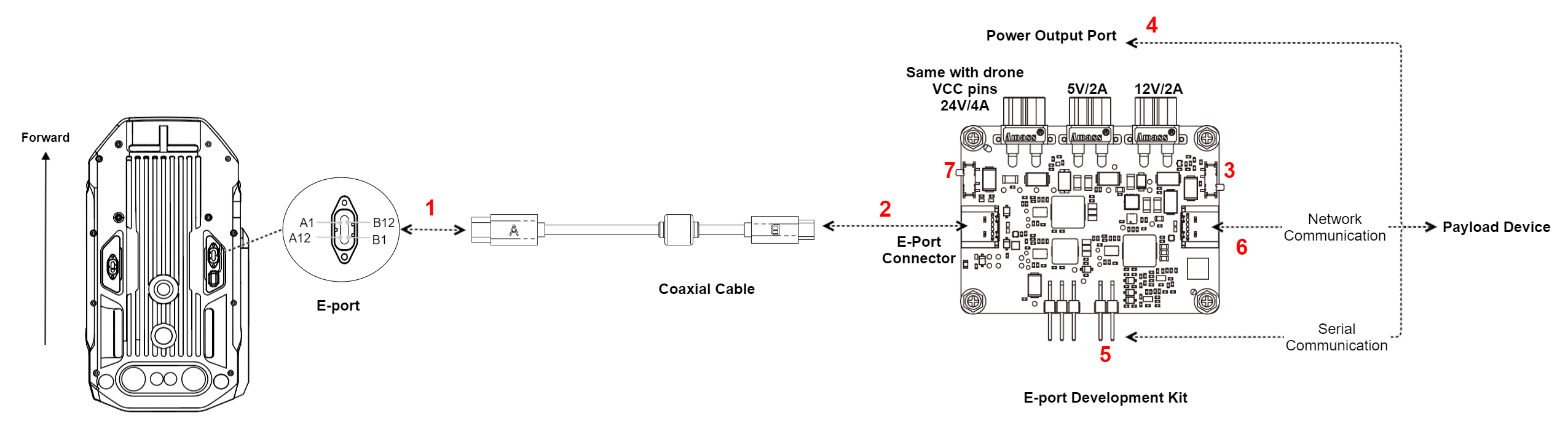
The schematic layout of the design up to this point is shown below:
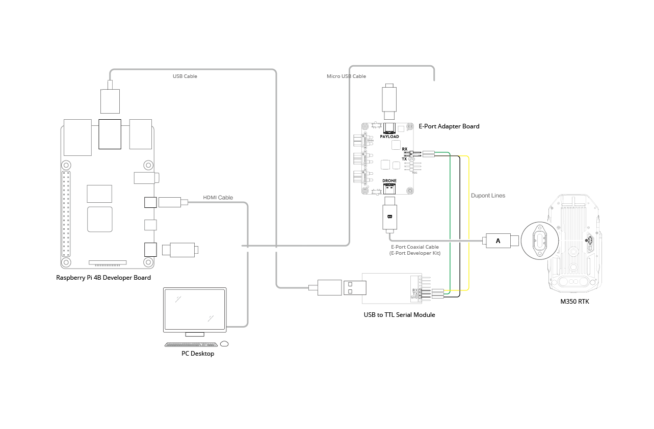
Wiring diagram from DJI's Developer Documentation.
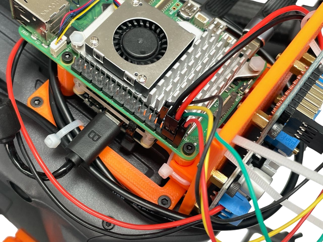
I2C connection
Using Dupont cables, connect each of the I2C lines to the appropriate pins on the Raspberry Pi (GPIO2 = Pin 3 and GPIO3 = Pin 5). Reserve pins 4 and 6 on the Raspberry Pi for the power input from the voltage regulator.
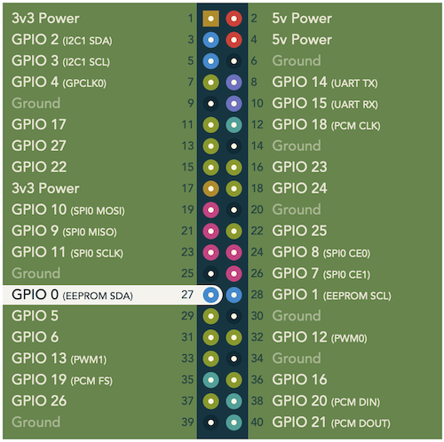
Finally, connect the sensor lines from each individual LightWare LiDAR to the I2C bus. At this point, the only unconnected cable should be the power cable output of the voltage regulator.
The power cable output from the voltage regulator should remain disconnected until the regulator is configured with the aircraft's power supply.
Aircraft installation
Secure the assembled kit to the aircraft using M3x8mm screws at the back and M3x15mm screws at the front.
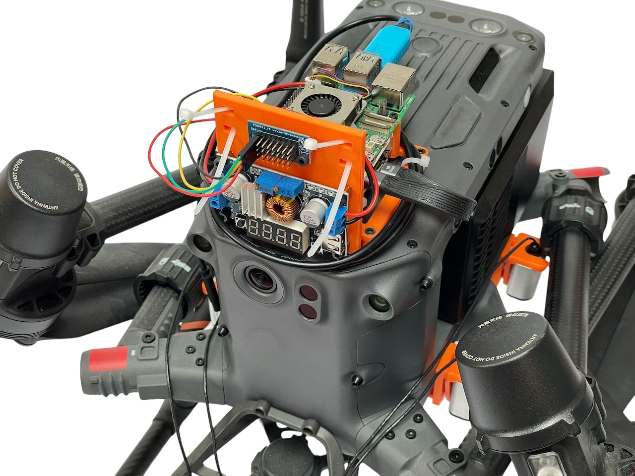
Once the development kit is securely mounted, connect the USB-C cable to the aircraft.
As previously mentioned, the USB-C cable used for DJI development is not a standard reversible cable. It has designated "A" and "B" sides, so be sure to follow the orientation guidelines in the DJI developer
documentation:
At this point, the kit will power on when the aircraft is activated, enabling data communication with the vehicle. However, please note that while the kit can connect to the aircraft, the Raspberry Pi might not receive its full power requirements until the voltage regulator is properly configured.
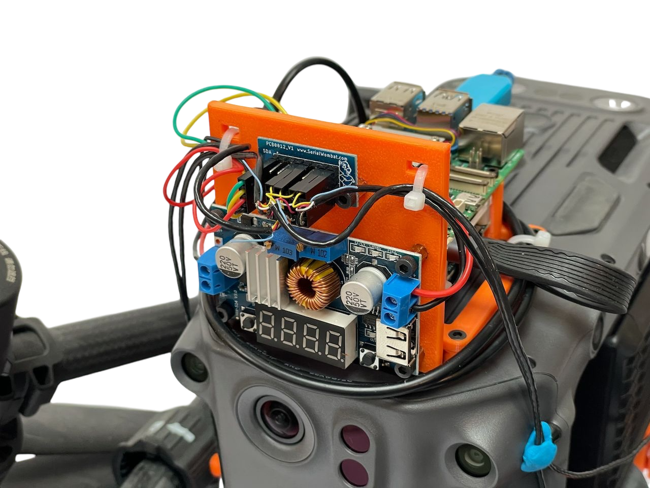
Voltage configuration
Ensure that the switches on the E-Port Dev Kit are set correctly by confirming that the switch at the drone's USB-C side is set to "on", and that the payload USB-C side switch is set to host mode.
On the voltage regulator, adjust the voltage by turning the potentiometer for the voltage limit. If unsure, refer to the markings on the PCB.
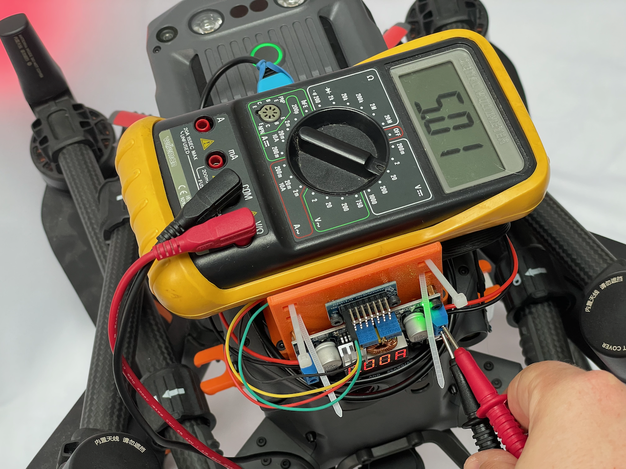
Power on the aircraft to confirm that the voltage regulator is operational. The model we've selected includes a digital display and indicator LEDs for monitoring.
The display on this voltage regulator is only for information; cycling through modes won't affect the output voltage.
While the aircraft is powered on, use a multimeter to measure the output voltage from the regulator's output terminal. Adjust thevoltage-limiting potentiometer until 5V is reached.
Power connections
Power off the aircraft before proceeding.
Connect the output power lead from the voltage regulator to the power pins on the Raspberry Pi. Refer to the pinout diagram above or the image below.
Connect the sensor lines to the I2C bus.
To tidy up, secure all loose cables with zip ties, making sure the setup remains easily removable for future maintenance and development.